
DFMPro for Sheet Metal Design Guidelines
DFMPro provides pre-configured design guidelines DFM rules for design which helps to develop better quality parts at reduced cost. Some of the common sheet metal design guidelines included are minimum distance between holes, cutouts, slots, distance between holes, cutouts, slots to part edge and bends, multiple bends in same direction, minimum bend radius, minimum radius of rolled hem, open hem and tear drop hem, minimum flange width, minimum size of slots, holes and many other design guidelines.
DFMPro sheet metal design guidelines are highly customizable and provides the flexibility to configure the available sheet metal design rules as per organization specific design rules. It also provides the ability to add new design for manufacturing rules easily into its existing database
Sheet Metal Design Guidelines
The section below contains examples of some design guidelines for sheet metal. These guidelines may help companies to avoid rejections and rework due to engineering errors leading to higher cost of quality and delay in the delivery to customer.
Minimum Distance from Extruded Hole to Part Edge

Extruding metal is one of the most extreme pressure applications in press working and generates lot of friction and heat. If an extruded hole is too close to the part edge, it can lead to deformation or tearing of the metal. It is recommended that the minimum distance between the extruded holes to part edge should be at least three times the thickness of sheet.
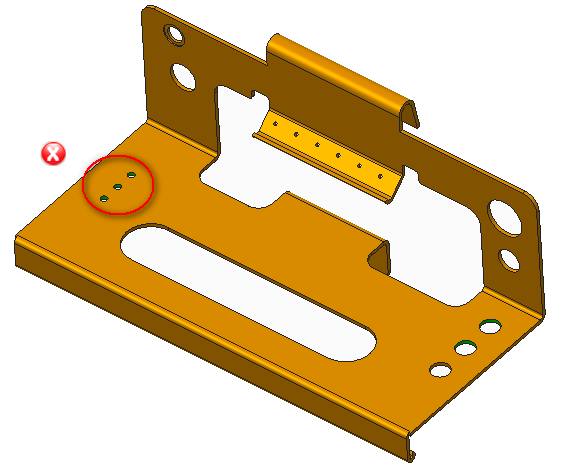
Minimum Distance Between Extruded Holes

Certain distance should be maintained between two extruded holes in sheet metal designs. If extruded holes are too close it can lead to metal deformation. It is recommended that the minimum distance between two extruded holes should be six times the thickness of sheet metal.
Minimum Distance Between Extruded Holes
Certain distance should be maintained between two extruded holes in sheet metal designs. If extruded holes are too close it can lead to metal deformation. It is recommended that the minimum distance between two extruded holes should be six times the thickness of sheet metal.
Minimum Hole Diameter
The diameter of the hole in sheet metal part should not be very small, small holes are created by piercing operation and for manufacture small holes, small sizes punches are required. Small hole size in sheet metal requires smaller size punching tool which may leads to break during the operation. It is recommended that the diameter of the hole should be equal or more than the thickness of the sheet metal.
Maximum Embossment Depth
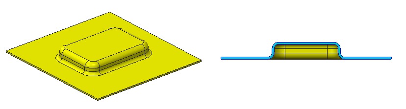 Embosses are small, shallow formed projections on the surface of stamped parts. During this operation, stretching is the main deformation mode resulting in high tension. Thereby the metal is subject to excessive thinning or fracturing. Consequently, the depth of the embossed feature is restricted by the material’s thickness and ability to stretch in addition to the emboss geometry.It is recommended that the maximum depth of embossment be less than or equal to three times material thickness.
Minimum Bend Radius
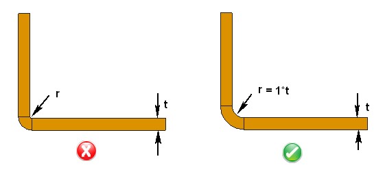
Minimum bend radii requirements can vary depending on applications and material. For aerospace and space applications, the values may be higher. When the radius is less than recommended, this can cause material flow problems in soft material and fracturing in hard material. Localized necking or fracture may also occur in such cases. It is recommended that minimum inner bend radius should be at least 1 times material thickness.
Curl Feature Guidelines
 Curling sheet metal is the process of adding a hollow, circular roll to the edge of the sheet. The curled edge provides strength to the edge and makes it safe for handling. Curls are most often used to remove a sharp untreated edge and make it safe for handling.It is recommended that:
- The outside radius of a curl should not be smaller than 2 times the material thickness
- A size of the hole should be at least the radius of the curl plus material thickness from the curl feature
- A bend should be at least the radius of the curl plus 6 times the material thickness from the curl feature
Hem Feature Guidelines
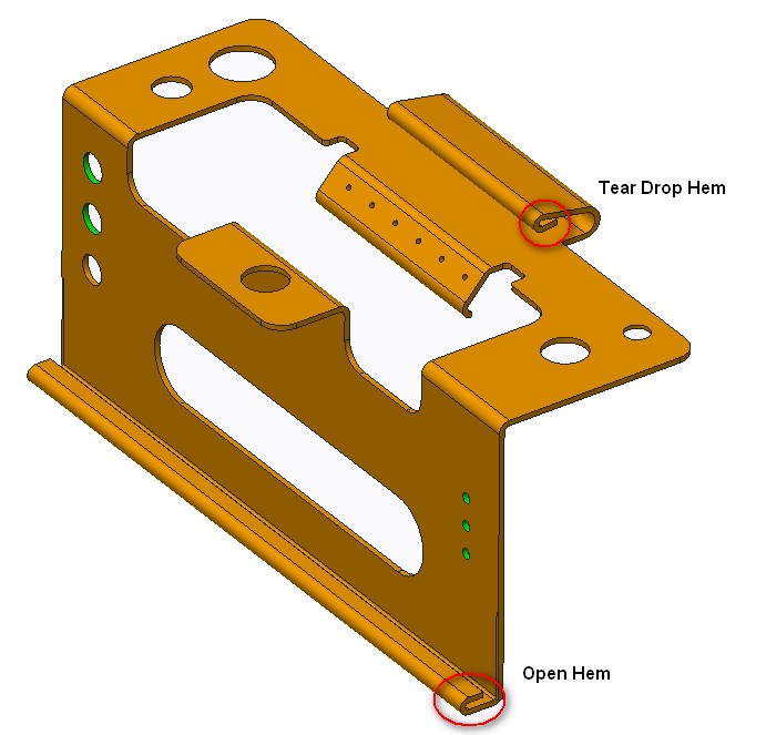 Hemming is nothing but to fold the metal back on itself. In Sheet Metal hems are used to create folds in sheet metal in order to stiffen edges and create an edge safe to touch. Hems are most often used to remove a sharp untreated edge and make it safe for handling. Hems are commonly used to hide imperfections and provide a generally safer edge to handle. a combination of two hems can create strong, tight joints with little or minimal fastening. Hems can even be used to strategically double the thickness of metal in areas of a part which may require extra support. It is recommended that:
- For tear drop hems, the inside diameter should be equal to the material thickness.
- For open hem the bend will lose its roundness when the inside diameter is greater than the sheet metal thickness.
- For bends, the minimum distance between the inside edge of the bend and the outside of the hem should be 5 times material thickness plus bend radius plus hem radius.
Notch Feature Guidelines

Notching is a shearing operation that removes a section from the outer edge of the metal strip or part. In case, distance between the notches to bend is very small then distortion of sheet metal may take place.To avoid such condition notch should be placed at appropriate distance from bend with respect to sheet thickness. Notching is a low-cost process, particularly for its low tooling costs with a small range of standard punches. DFMPro sheet metal design recommendations for Notch Feature:
- Notch width should not be narrower than 1.5 * t
- Length of notches can be up to 5 * t
- Recommended corner radius for notches should be 0.5 * t