
DFMPro for Injection Molding Design
DFMPro design for manufacturing software helps to check for industry standard DFM practices for injection molding design, right inside the CAD environment. This helps produce parts economically at a better quality and shorter lead time. Users can validate the injection molding designs to check for uniform wall thickness, recommended rib parameters, appropriate draft angles on core and cavity surfaces, undercuts, thin steel conditions on mold and many other common rules.
DFMPro provides flexibility to configure the available injection molding design guidelines. It also provides the ability to add new design rules requiring very basic programming knowledge.
Design for Injection Molding Guidelines
Injection molding has been one of the most important fabrication tools for the plastics industry since a very long time. Today, it’s almost impossible to do anything without using injection molded parts. They are used in automotive interior parts, electronic housings, housewares, medical equipment, compact discs, and even doghouses. Below are certain standard guidelines which can be referred to while designing parts for injection molding. Please note that these guidelines are general depending on particular requirements, it may not always be possible to follow all the guidelines.
DFMPro Design Guidelines for Ribs
Recommended Rib Parameters
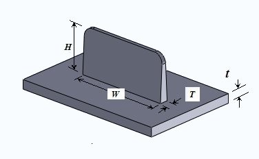 Rib features help in strengthening the molded part without adding to wall thickness. In some cases, they can also act as decorative features. Ribs also provide alignment in mating parts or provide stopping surfaces for assemblies. However, projections like ribs can create cavity filling, venting, and ejection problems. These problems become more troublesome for taller ribs. Ribs need to be designed in correct proportion to avoid defects such as short shots and provide the required strength. Thick and deep ribs can cause sink marks and filling problems respectively. Deep ribs can also lead to ejection problems. If ribs are too long or too wide, supporting ribs may be required. It is better to use a number of smaller ribs instead of one large rib.
Minimum Radius at Base of Ribs
A fillet of a certain minimum radius value should be provided at the base of a rib to reduce stress. However, the radius should not be so large that it results in thick sections. The radius eliminates a sharp corner and stress concentration. Flow and cooling are also improved. Fillet radius at the base of ribs should be between 0.25 to 0.4 times the nominal wall thicknesses of the part.
Draft Angle for Ribs 
Draft angle design is an important factor when designing plastic parts. Such parts may have a greater tendency to shrink onto a core. This creates higher contact pressure on the core surface and increases friction between the core and the part, thus making ejection of the part from the mold difficult. Hence, draft angles should be designed properly to assist in part ejection. This also reduces cycle time and improves productivity. Draft angles should be used on interior or exterior walls of the part along the pulling direction. It is recommended that draft angle for rib should be around 1 to 1.5 deg. Minimum draft should be 0.5 per side.
Spacing Between two Parallel Ribs
 Mold wall thickness gets affected due to spacing between various features in the plastic model. If features like ribs are placed close to each other or the walls of the parts, thin areas are created which can be hard to cool and can affect quality. If the mold wall is too thin, it is also difficult to manufacture and can also result in a lower life for the mold due to problems like hot blade creation and differential cooling. It is recommended that spacing between ribs should be at least 2 times the nominal wall.