
Design For Assembly Software- DFMPro
Fastener Accessibility
Rule: To access the fasteners used in assembly, fastener tool height and diameter should be considered and it should equal to a user specified value.
Explanation: In order to achieve best practices in case of Design for Assembly & Dis assembly process, it is necessary to ensure sufficient space around the fastener to access the fastening tool for ease of fastening or extraction.
User has to provide following inputs for the rule Fastener – The name of the fastener to be validated for the rule. Fastener should be selected from a dropdown list. The drop down list is populated from the fastener database.
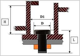
Fastener Clearance
Rule: For a fastener, the axial clearance and/or radial clearance should be greater than or equal to the value specified.
Explanation: User has to provide following inputs for the rule. Fastener – The name of the fastener to be validated for the rule. Fastener should be selected from a drop down list. The drop down list is populated from the fastener database.
- Axial Clearance – Expected axial clearance for the fastener.
- Radial Clearance – Expected radial clearance for the fastener.
Note: Radial clearance is computed for all components except the last component. It is assumed that the last component (nut / threaded boss) has thread engagement with the fastener.
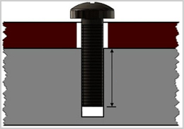
Fastener Engagement Length
Rule: Fastener engagement length (axial distance between top of the boss and base of the screw) should be greater than or equal to user specified value.
Explanation: User has to provide following inputs for the rule.
- Fastener – The name of the fastener to be validated for the rule.
- Engagement Length -Expected engagement length for the fastener
Fastener Database User can add, remove or edit fastener(s) in the database from the configuration dialog available in rule manager.
Hole Alignment Guidelines in Design for Assembly
Explanation: Due consideration needs to be provided for appropriate alignment of holes used for fasteners to avoid problems during assembly. This rule checks if holes designed in CAD models are aligned appropriately with other holes in mating components. Only holes opening out on external surfaces are considered for checking alignment. Accessibility condition is not checked. Following cases are identified and flagged –
- Through hole on a component blinded by a surface on another component.
- A pair of holes with parallel axes having axial misalignment. Only cases with holes having partial or complete overlap are considered.
- A pair of holes with inclined axes (angular misalignment). Only cases with holes having partial or complete overlap are considered.
Currently only holes opening on mating surfaces and having diameters within 50% of each other are considered for alignment check.
Recommendations: Design holes taking into account their position and location in the assembly in relation to the surrounding components.
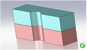
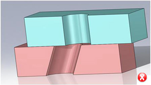
Interference Detection
Rule – To achieve desired functionality and ease of assembly interference between assembly components must be avoided.
Explanation: This rule identifies interference conditions between assembly components, Interference detection is most useful in complex assemblies, where it can be difficult to visually determine whether components interfere with each other.
Recommendations: By default, all components of the assembly are selected for analysis. Generally, it is expected that nominal dimensions of components should not result in interference. Interference between the following part types will be checked:
- Solid to Solid
- Part to sub-assembly
- Sub-assembly to sub-assembly
Additional Option: Ignore interference results in the threaded region. Results outside the region will be reported.
Interference Detection
Rule: Minimum clearance between any two components in the assembly should be greater than or equal to the specified value
Explanation: For the rule input, following options are available. Either or both options can be selected for checking the clearance.
1. Default clearance This input clearance value is checked between all the pairs of parts in an assembly.
2. Minimum clearance between selected pairs This option can be used to check the clearance between any two pairs of components.To input a clearance value in the rule configuration window, follow these steps:
- Left click on a cell in the table and type in the component name in columns “Component 1” and “Component 2” OR Right click on a cell and select the component file
- Input a clearance value in the third column
Clearance between the following types can be checked:
- Part to part
- Part to sub-assembly
- Sub-assembly to sub-assembly