
DFMPro for Machining Design Guidelines
DFMPro® provides pre-configured machining design guidelines and industry best practices. The guidelines for processes like drilling, milling and turning. DFMPro is highly customizable framework and provides the flexibility to also configure the existing set of machining design guidelines or add new guidelines as per organization specific best practices.
Examples of Drilling Design Guidelines available in DFMPro
Deep Holes
Deep, small diameter holes should be avoided as they are difficult to machine. Small diameter drills tend to wander and are prone to breaking. Chip removal also becomes difficult while drilling deep holes. Therefore it is recommended that the hole diameter to depth ratio should be less than 3.
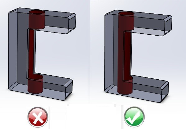
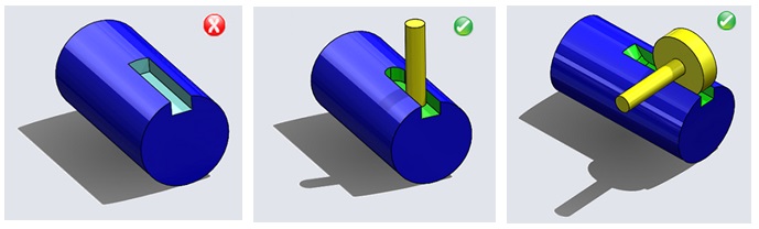
Entry/Exit Surface for Holes

Drills should enter and exit surfaces that are perpendicular to the centerline of the hole. If the drill tip contacts the non-planer surface, then tip will wander as its axis is not perpendicular. Also exit burrs will be uneven around the circumference of the exit hole, which can make burr removal difficult.
Holes with Flat Bottom
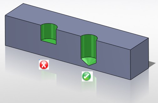
Blind holes should not have a flat bottom. Flat bottomed holes cause problems with subsequent operations (for example: reaming). A standard twist drill creates a hole with a conical bottom.
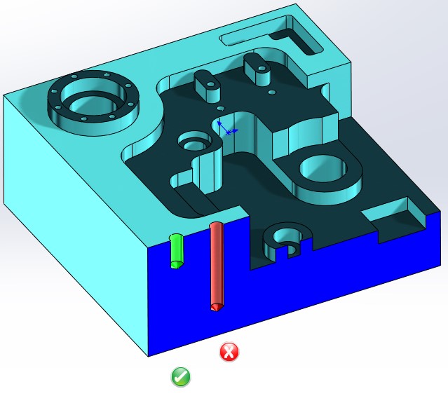
Holes Intersecting Cavities
Holes should not intersect a cavity. If an intersection is unavoidable, at a minimum, the center-line of the hole should be outside the cavity. During machining, the drill follows the path of least resistance when it intersects a cavity. There is a good chance that the drill will wander when it re-enters the material.
Partial Holes
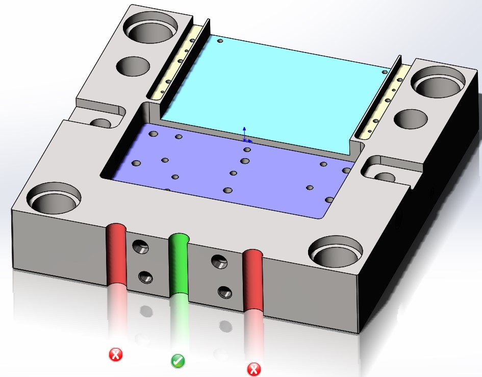
Avoid partial holes as there are high chances that drill will wander if a large portion of the hole is outside the material. The problem can become even more severe if the axis of hole is on or near the edge of the material. If partial hole is unavoidable, then ensure that at least 75% of hole area should be within the material.

Specify standard hole sizes as they can be created using a standard drill. Unusual hole sizes are not recommended as they require custom tools and increase the cost of manufacturing through purchasing and inventory. Reducing variations in holes size will further reduce assembly accessories like fasteners, pin, rivets, etc.
Design Guidelines for Milling
Milling is one of the most flexible and well known method of machining. Due to the high tolerances and surface finishes that milling can offer, it is ideal for producing parts with precision features and shapes.Milling is typically used to produce parts that are not axially symmetric and DFM guidelines recommend avoiding sharp internal corners inside pockets when it is to be manufactured using milling process. Know about machining design guidelines by DFMPro in the video.
Deep Narrow Holes
Try to avoid pockets and slots that are narrow and deep. Longer tools are more prone to breakage and chip removal becomes difficult, especially when the pockets and slots are blind.
Deep Radiused Corners

Designers should design milling areas such that longer end mills are not required to machine it.Longer end mills are prone to breakages and chatter, requires longer machining time and results in increased tool vibrations. Vibration creates uneven wear on cutting tools and thereby shortens tool life.
Sharp Internal Corners

Rounded corners provides number of advantages such as less stress concentration on part and tool, few operational steps and reduced scrap rate. Sharp inside corners cannot be produced by milling and require more expensive machining methods like EDM. When designing a three-edged inside corner, one of the inside edges should be radiused. It is advised to avoid sharp corners and use fillets and radii.
Narrow Regions In Pockets
It is recommended to avoid features that are too close to each other such that the gap between them is too narrow to allow milling cutter to pass through them. If narrow regions are unavoidable, then they should not be very deep. The size of the milling cutter is constrained by the smallest distance between the faces of the feature. Small diameter cutters are prone to breakage and chatter. Hence larger diameter, shorter cutters are generally preferred.
Side Radius and Bottom Radius

Use of standard side radius and bottom radius for milling features will ease manufacturing of milling features with standard available milling tools. For reducing, machining cycle time and tool setup cost, it is recommended to avoid non-standard side radius and bottom radius. It is recommended to use single standard side radius and single standard bottom radius.
Angular Milling Faces

Side and bottom faces of milling features separated by bottom fillet should be at 90º to each other to allow production with an end mill having bottom corner radius. Machining of angular faces require multi-axis machining, which leads to higher machining cost.
Tool Accessibility

Features should be accessible to the cutting tool in the preferred machining orientation.
Design Guidelines for Turning
In turning operation, design the part for easy fixturing and secure holding. A large, solid mounting surface with parallel clamping surfaces should be provided to assure a secure setup. Avoid designs that require sharp corners and sharp points in cutting tools because these make the tools more subject to breakage. It is preferable to avoid interrupted cuts, as they tend to shorten tool life.
Blind Hole Relief

Provide tool relief for the bottoms of blind bored holes.Tool relief at the end of a bored hole will simplify the operation of honing, boring, reaming, and grinding and reduce costs. The minimum amount of relief is expressed as a percent of the diameter of the pre-bored. It is recommended that relief at the end of bored hole should be greater than or equal to 3% of the diameter of bored hole.
Keyways
It is recommended to use radiused keyways at the end of a key-slot. Radiused keyways need to be milled with end milling cutters, so that the rounded end or ends of the key may fit the ends of the keyway. The cutter’s diameter should always be equal to the width of the key. Keyways should be radiused at the end to suit the cutting tool. If the end of keyway is radiused in such a way that it could be cut by a slotting cutter it will improve the speed of machining keyways.
Long – Slender Turned Parts

For long-slender part, it is recommended to center drill the free end and use a dead or live center in the tailstock to support it. Without support, the work piece would bend and displace away from the tool. Also, it may loosen the grip of chuck jaws on work piece and cause injuries or accidents. Turned parts should be designed such that a tail stock support is not required. This is done by designing the part to be stubby rather than long with a high aspect ratio. It is recommended that, ratio of total length of part to its minimum diameter should be less than or equal to 8.
Minimum Internal Corner Radius

It is recommended to avoid sharp internal corners and provide large inside radius so that a tool with large nose radius can enter easily. A tool with large radius is less prone to breakage. A turn-down surface at right angles to an un-machined (cast) surface might lead to burrs. The minimum radius on internal corners of a turned part determines the cutting inserts that can be used.
Outer Diameter Profile Relief

Profile relief on the outer diameter of a turned part helps in smooth turn-machining of part. The turned contour should allow easy tracing with a minimum number of changes of stylus and cutting tool. Grooves with parallel or steep sidewalls are not feasible in one operation. Contours inclined upto an angle of 58° from the axis of the part are feasible for a cutting tool (and stylus).
Symmetrical Axial Slots

It is recommended to design axial slots and keyways such that they are symmetrical about the turn axis. The design for machining guideline identifies whether the width of axial slots and keyways is symmetrical about the turn axis or not, a condition which is likely a result of an error during modeling. If width of axial slots and keyways is not symmetrical about the turn axis, then the part will face problems while coupling with other turn parts.